Making a Footswitch
Pretty basic beginner project. But its a good one, generic latching foot-switches are pretty expensive for how simple they are. Amp foot-switches work by connecting and disconnecting the ground/sleeve to the hot/signal.
You need; some kind of enclosure, SPDT switch (DPDT/3PDT etc. works fine), mono jack socket, guitar cable
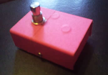
Drilling the enclosure is the hardest part really. Take your time, start with a small bit and work your way up, the enclosure i used was pretty thin aluminum, it was quite tricky not to shred my face with the shavings.
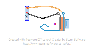
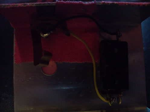
Wiring it should take about 5 minutes. Simply connect the sleeve on the jack socket to the pole of the switch, and the tip to one of the throws, leave the other alone.
You can solder a guitar cable directly to the switch for the same effect, i prefer using the jack since its easier to swap if the cable gets ran over, and you could pretty easily tug/snap the wires from the switch if you’re using it on stage and you dont have some stress relief on the cable.
There you go, a footswitch for £5. 🙂
Dual/stereo Footswitch
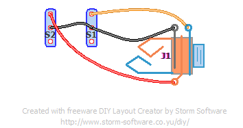
Dual footswitches can be made pretty easily too, you just need an extra footswitch, a stereo jack socket and a stereo instrument cable (can be identified by 2 black rings on the tips of the plugs). The extra switch is usually used to activate boosts/bright/fat/whatever switches, or reverb more commonly. Of course this is only if your amp supports that, it should say on the back where the footswitch socket is.
Connect both the poles for the switches together, and back to the sleeve of the jack, and one throw from a switch to the ring of the jack, and one to the tip.
Adding an LED
Adding an LED seems unnecessary to me, after all, the difference between the clean and dirty channel should be quite obvious. Some amps (Usually the ones that have LEDs on the footswitch recommended for them) have a small current running through the footswitch output, meaning the footswitch doesnt need any external power for the LED. So its just a case of adding a resistor and LED between the ground and hot, make sure you orientate it the correct way around. You can check this with a multimeter.
The resistor is just to stop too much power going to the LED and popping it, 330ohm should be fine, if its too bright increase it, it its too dim, lower it.


“An insightful blog post right there mate ! Thanks for the post .”
January 18, 2013 at 11:32 am
“Someone essentially lend a hand to make seriously posts I might state. This is the first time I frequented your web page and up to now? I surprised with the research you made to create this actual put up extraordinary. Magnificent process!”
January 21, 2013 at 6:08 pm
“That durian even if it smelly and stinks, it still taste delicious. I tried it and I had to stop breathing just to eat that fruit. Later on, I realized the smell stayed on my mouth. After all those, I had a fun experience!”
January 21, 2013 at 6:08 pm
How would one wire in a power source for the LEDs if needed? Would a dpdt switch be used instead?
February 20, 2017 at 1:32 am
Hi, great blog. I’ve tried the last wiring (the one with the led) and it doesn’t work. The led goes ON/OFF but it doesn’t change between channels. For those who are interested, follow these steps:
1) Hot jack goes to the third lug of the switch (like in the wirings above). In this same lug you need to put the LED’s anode (+) . You usually add a resistor to the LED to prevent it from blowing away and reduce the brigthness, so actually it is the end of the resistor which goes into this lug
2) Ground jack goes to the second lug of the switch. In this same lug you have to put the LED’s cathode (-)
That’s exactly what I have made and it’s working flawlessly in my Orange AD30HTC. The LED goes ON when channel two is engaged.
I hope it helps 😉
Nono St.
July 19, 2017 at 6:53 pm