Small Clone Mods
I was looking around for some mods for the small clone and came across this post.
http://experimentalistsanonymous.com/board/index.php?topic=1578.0
Naturally turning my chorus pedal into a vibrato/tremolo pedal was pretty exciting. So i gave it a go and can report some great results.
There was a few personal touches i wanted to make. First off, i wanted to be able to use the tremolo dry without the chorus/vibrato effect, and i found the pot used to dial in/out the dry signal pretty useless as the effect was pretty subtle.
Wet/Both/Dry Switch (Dry, Chorus, Vibrato)
You need; A 3 way rotary switch with 2 poles minimum, you could also use an on/on/on 3 position dual pole toggle switch.
In the mod the vibrato effect was accomplished by switching in/out the resistor that controls the dry output level (R18). So it was simply a case of finding the resistor that controls the wet output, which is conveniantly, right next to it, (R17).
Using the same principal as the dry lift, pull one leg of the resistor off the board and hot glue it in place. I wanted to use a rotary switch which will allow me to switch between dry signal (which seems to have a slight prescence and brightness boost over the bypassed signal), chorus and vibrato. I used a 4 pole 3 throw rotary for this.

This should make sense, the central position would be both resistors connected (full chorus sound). The left position will disconect R18 just leaving R17 connected, vibrato, switched to the right R17 is disconected and R18 is connected, so you get just the dry signal.
Job done, bit of a squeeze fitting it in the enclosure though. Use some tape to stop the lugs of the switch touching any of the legs of the components/anywhere it can short out.
If you want to use an ON/ON/ON switch or ON/Z/ON do it like this
The center position is the stock sound (all vertical poles are connected), up would disconect R18 and connect R17 so you get vibrato, down would disconect R17 and connect R18 so you get dry signal.
Small Clone Flanger Switch Modification
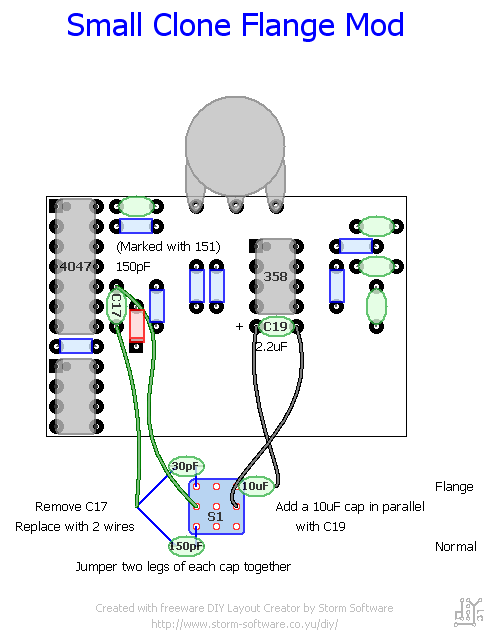
You need; 10uF capacitor, 150pF capacitor, 30-60pF capacitor, on/on DPDT/3PDT switch
Next up, id been reading some info on turning my small clone into a pseudo flanger. So i looked into the main differences of the sound qualities of a flanger and chorus, which are quite similar in design.
The sweep is a lot slower. Which would mean id have to slow down the LFO. The big electrolytic polarized 2.2uF C19 cap controls the LFO speed, just below the LM358. To slow it down you just have to add on a larger value cap in parallel, i used a 10uF cap mounted to a switch. If youre using a polarized cap (In general most electrolyics are, and tantulums. The longer leg is positive) make sure you align the legs correctly to match up with the cap allready there (+ side to +, – side to -).
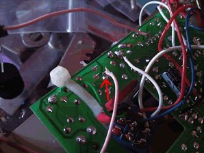
Just attach wires to the back of the PCB where the cap sits, then take one wire to one leg of the 10uF cap, the other leg should be mounted to a lug on the switch, the other wire from the PCB should go to the lug directly above or below the other wire, though really it doesn’t really matter specifically which lug, as long as they are aligned vertically it will still add the cap in parallel.
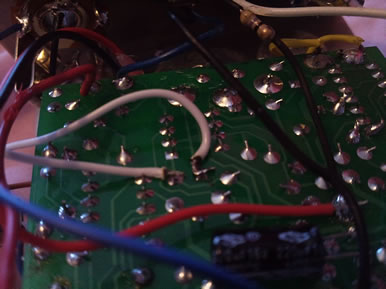
Below shows the location of the two wires (white) leading to the C19 cap on the back of the PCB.
Here’s a diagram explaining on/on DPDT switches, 3PDTs work the same, just add another column of lugs. With an ON-ON-ON switch you will have a central position that will connect all 3 vertical lugs together.
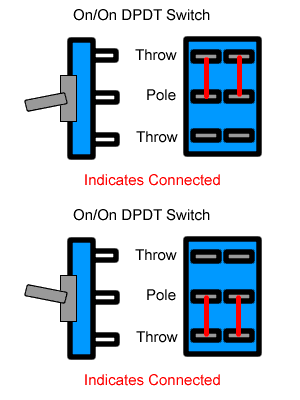
This will give you a total capacitance of 12.2uf. Provides a pretty good range of speed, at the higher settings it gets back into the stock range of chorus speed below about 1/4″ of a turn of the speed knob. If you want the ability to get a faster flange try a 6,8uF. Though personally, i think it sounds too much like a chorus at higher speeds.
Secondly, the HF clock uses a smaller capacitor to shorten the “delay time”. Chorus, flange, phase are all delay based effects, all of which are accomplished by a delay time in milliseconds. Really if you have a delay pedal you can simulate chorus and flange if you have the ability to fine tune, though it doesn’t tend to sound as rich as a true chorus/flange pedal.
To make it more flanger-y i need to make the delay time smaller by swapping the cap that controls this. Stock this is the Orange Ceramic C17 cap directly to the right (in parallel) of the 4047. It’s marked with 151, (15+1 ‘0’ at the end, so 150pF) . This needs to be replaced with a smaller cap value, i used 30pF, i imagine anything from around 30-60pF would work.
And a 3PDT toggle switch that allows me to change both caps at the flick of one switch, really you could do that with a DPDT anyway just ignore the middle row on the diagram, I just had a 3pdt lying around.
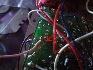
Just short one of the legs from both the 30pF and 150pF together and connect them back to C17 where one of the wires was meant to go. Then add the other leg from each cap to the top/bottom lugs of the switch. Make sure the 30pF is turned on with the 10uF for it to work properly. Then the other wire from the PCB should be in the center lug between the two caps. Here’s the two wires leading to were C17 was.
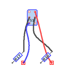
Here’s a diagram showing this part of the mod. Everythings not in the right place and its only the top of the PCB, but it’s just to give you an idea of where everything is and how to orientate the switch.
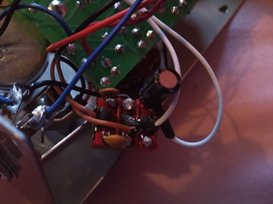
You could mount the 30pF/150pF straight to the switch if you’re using a 3PDT. Thats how i actually did it, and this is how my switch looks. (It’s a little messy, but id already used this switch for another build and didnt bother cleaning it up…)
If you want some more range/versatility you could use two separate switches for shifting the predelay and changing the LFO speed.
An idea would be to use an on/on/on switch for the 30/150pF caps, then you could have a central position for a deep chorus (180 pF total) sound and a thinner chorus sound with the 30pF without slowing the range right down.
Then stick the 10uF on a separate SPDT switch.
Just a note; This mod will slow the tremolo right down, and the vibe setting wont sound any different from the dry setting wtihout the regen control.
Adding a feedback/regeneration control
You need; 100k reverse/anti log pot, 33k resistor
This alone will make an okay sounding flange, subtle but definitely usable, you wont be getting much in the way of jet plane swooshes. So we need to add some regen/feedback for more presence of the flange sound and thickness, we do this by creating a feedback loop in the delay section of the pedal feeding back into the input of the circuit. In a delay pedal this would be the “Repeats” control.
Figuring out how to get good sounding results caused a lot of head scratching and ear piercing whining noise from the pedal at 12am, i knew where about to tap the points for feedback from some online research, none of them worked how i wanted, in the end it was just trial and error, and figured it out. Bear in mind, this doesn’t work perfectly, its best used in conjunction with the dry/chorus/vibrato switch i explained above, if you just want some fat flanger sounds without buying a separate pedal, this will do what you want.
The first point for the feedback loop will be at the junction of the .1uF cap and 220k resistor if you’re looking at a schematic. This is where we tap the delayed signal from.
The second point is pin 6 of IC1b (the 4558), when we’re looking at it from the back of the PCB this is the 3rd pin down of the IC chip on the left hand side. This is where the signal is fed back.
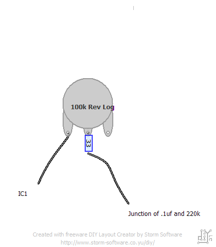
Connect these two points together with a 100k pot (I recommend using reverse log/anti-log if you can find one, most of the regeneration sounds will come in at the end of a linear pots travel, so the reverse audio pot is ideal.) set up as a variable resistor, one wire to the center, the other to the right hand side, so turning the pot all the way to the left results in no regen. This alone will work, but cranking the pot to full will result in some horrific oscillation. Which we dont want (Well i dont, you can see how it sounds if you want, its pretty loud and horrible i assure you.).
So we have to limit the amount of signal going back into the IC, a 33k resistor on the wiper (central lug) of the pot will limit the signal to the brink of oscillation. You may have to play about with the value since my clones allready pretty heavily modded, a higher value will limit the signal more, a lower will allow more signal to pass through. Generally this is done with a trimpot in flange pedals, so you can dial it in just right, i reccomend doing that if you have the room inside.
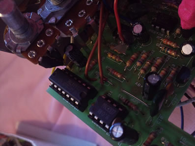
Heres what it should look like from the back of the pot.
For the best results with this mod, i recommend doing the vibrato mod along with it (the dry/chorus/vibrato mod further up the page). The regen doesn’t seem to do much with it in the stock setting without either of the resistors pulled, in fact it seems to kill the flange at the highest point, but with it turned to the vibrato/dry setting you will get lots of wonderful synthy vocal sweeping.
It gets a bit subby at the bottom end of the sweep, so you might want to consider tacking on a high pass filter cap (2.2nF should do) in the path of the feedback as well. The regen will do some pretty interesting sounds with the vibrato/chorus too. Give it a try, let me know how you like it. 🙂
Update: Ive had a report from someone who claimed that with the pedal bypassed flange/vibrato could still be heard, if you have this problem its because your small clone is an older one and is not true bypass. You need to replace the DPDT with a 3PDT switch and wire it for true bypass switching.
Disclaimer; Im not responsible for the death of you (unlikely) or your small clone (possible if you let any wires short out on the enclosure, i encourage using heat shrink, hot glue and electrical tape to prevent this from happening), feel free to post in the comments and ask for help, but these mods work fine for me, so do it at your own risk :).

Very interesting…I’ll try it along with few other mods i found to be useful. Hope it will work for me, as it worked for you.
May I ask for some help if needed?
February 19, 2011 at 1:53 pm
No problem just ask here or send me an email through the contact page.
February 19, 2011 at 2:24 pm
OK than… I already started with depth knob, and “Wet/Both/Dry Switch (Dry, Chorus, Vibrato)”, with the parts I have at home…
I’ll keep you informed…
February 19, 2011 at 3:08 pm
Hello, i did the vibrato mod, works very well! I did the feedback mod (but without 33k) and no difference (oppositly to your excellent video), just no sound whrn the pot is all the way up. I think i missed something, you talk about a 2.2nF but i don’t really understand.
April 5, 2011 at 6:54 pm
Without more details i cant really help, double check youve connected the right pin of the IC and to the right place back to the PCB.
The feedback mod will only work with the vibrato/dry setting engaged, did you try that?
The 2.2nF acts as a high pass filter to remove some of the low end, it isnt needed, but just tack it on somewhere in the feedback path so it doesnt get too thumpy.
April 6, 2011 at 12:12 am
Hello,
here is a link of the feedback mod i did : http://img684.imageshack.us/i/cloner.jpg/
Yes i engaged the vibrato mod (actually i only play with that now)
April 9, 2011 at 10:01 am
The red wire on the pot is leading to the wrong place it looks like.
Should lead to the pad underneath (Where the traces lead to the negative (square) pad of the electrolyic capacitor.) on the picture if you double check against my pictures.
April 9, 2011 at 5:20 pm
excellent, thank you very much, it works very well
April 10, 2011 at 10:53 am
Hey dude! Do you have a diagram of flange mod with DPDT toggle switch? because I don’t have a 3PDT stomp switch. Thnx!
April 2, 2015 at 8:14 pm
Hey there, what schematic were you looking at? Looking at the tonepad schematic there I can’t find a 0.1 uF cap in this circuit: http://www.tonepad.com/getFile.asp?id=97.
I’m having issues getting the feedback pot to work as well. Currently I have the PCB leg of the pot connected to the 220k, 1uF, 20k (vibrato resistor) junction. But this is just seems to be acting as a volume control. My circuit a newer version, so pictures aren’t useful since the traces look different. Any response appreciated, thanks!
September 12, 2023 at 7:46 pm
Closing the loop my necro-reply…
The 220k and 1uF junction I mention is correct for the feedback regen. The other leg from the pot needs to go to pin 2 of IC1, not pin6.
Thank you becky for a great mod!
February 22, 2024 at 6:59 am
I’m a bit rusty so great work and thanks for sharing . Nice people are still enjoying these mods!
February 22, 2024 at 7:26 am
Very cool mods. Any possibility of getting a schematic of the mods?
November 4, 2023 at 3:12 pm